Building Information Modeling in Architecture
This is a follow-up on my previous
video which was about modeling Beethoven Concert Hall designed by Zaha Hadid.


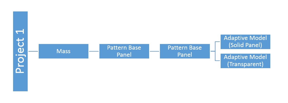
For that project, I created a mass then created adaptive component to apply on it. However, at the end, I had to select the components one by one and either change them to another panel or change their instance parameters. So, I decided to benefit from Dynamo and do some automation. The objective is to randomly select a portion of panels and replace them with other once, again a random basis.
Since we might need to change certain percentage of panels on each surface, I initiate the graph with selecting the divided surface. I am using a slider to change the percentage of panels that needs to be changed, then using a "Random List" node I make a list of random indices within the range of the selected surface.

Sine there is no replace node in Dynamo, I need to create new panels in the same location as the existing ones and then erase the existing panels. So, I use a node to retrieve the location of the existing panels. The new panels are created using the same location points. Then, the existing panel will be erased by use of custom node because Dynamo does not have an erase node.

I just need to mention that random selection is done by creating a list of random numbers which would be the indices. After randomly selecting a panel, it can be replaced by any of four existing panels and this selection needs to be done randomly as well. So a string of random integers within the range of 1 to 4 is created and the replacement is selected based on the associated number using a set of conditional statements.

The next step is to modify the parameters of created panels, again on a random basis. Another string of random integers within the range of 1 to 4 is created to drive the base vertex parameter of the new panels.

The number of solid and transparent sections of each panel needs to be modified randomly as well. Since this is driven by a set of binary parameters, another process is used to generate random string. Briefly, if a random integer within the range of 0 to 7 is written in binary mode, a string of 3 binary numbers is generated.

The main challenge in this process is about the nature of Dynamo. When Dynamo graph is run on a surface, it works perfectly for the first time but if the same graph is run on another surface, the panels created in the first run will be removed. It seems that Dynamo remembers what it creates to change it again and again. The solution to this problem is to delete the node that creates the panels and place a new node there. Then rewire it the same way and run it again.
Also, after loading the mass into the project, I decided to change the color override of glasses. The challenge was that the glass element was not separate from the frame when I created them in the first place and I needed to recreate the combination using a separate family for the glass part.